Every asset. Every stage. One signature at a time.
Track L1 to L4 on each asset: documents, checklists, sign-off, parties and issues, all tied to the drawing so nothing lives in a spreadsheet copy.
What do you want to do?
Jump straight to the answer
Overview
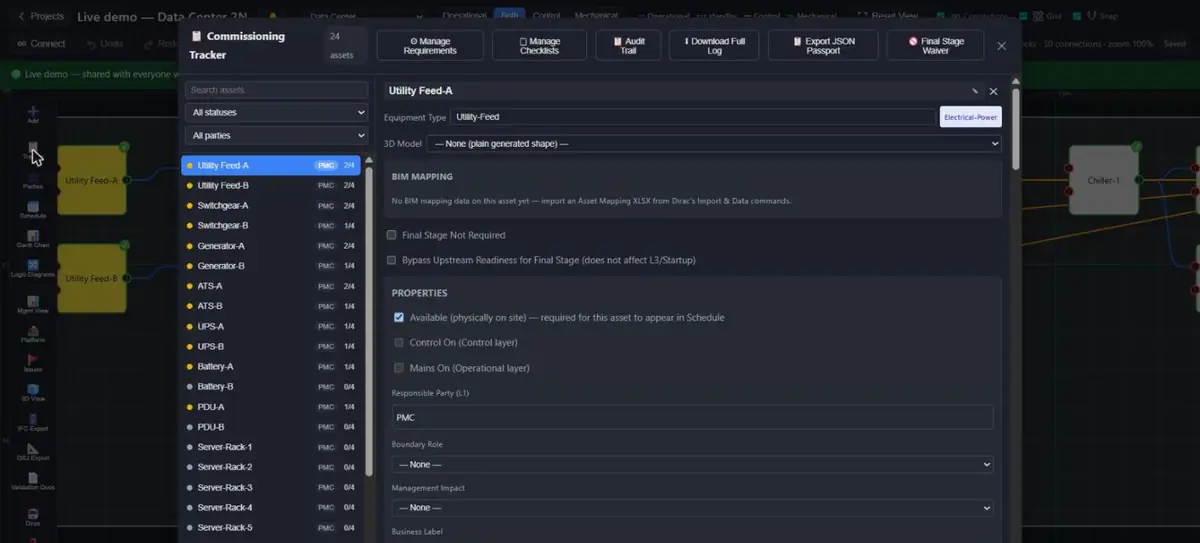 1234
1234- Search and filter by status or party
- Every asset with its stage count, for example 2/4
- Requirements, checklists, audit trail, full log, JSON passport, final-stage waiver
- Available, Control On and Mains On: the states the whole project reads
The Commissioning Tracker is opened per-asset from the canvas and records, for that one asset: progress through its four commissioning stages, which documentation requirements and checklist items are complete, who's assigned as the responsible party, and the sign-off record for each stage. It reads and writes the same project data everything else in Massive Dynamic uses — nothing is a separate import.
Opening the Tracker
Project modes
Massive Dynamic supports three project modes, each with its own four-stage vocabulary:
| Mode | Stages |
|---|---|
| Data Center | L1 Factory Acceptance Testing · L2 Installation & Pre-Startup · L3 System Start-up · L4 Performance Testing |
| Pharma | DQ Design Qualification · IQ Installation Qualification · OQ Operational Qualification · PQ Performance Qualification |
| Project Management (generic) | L1 Design — IFC Issued · L2 Procure — Contract Awarded/FAT Done · L3 Install — Pre-functional Check Complete · L4 Test — Functional Performance Test Done |
Layers in Project Management mode
The three connection layers keep their engineering names in Data Center / Pharma / Substation mode and are renamed — everywhere on screen — in Project Management Only mode. Nothing underneath changes: same wires, same ports, same converter ticks, same gates, same scheduling rules. Only the words do.
| Engineering modes | Project Management mode | A wire on this layer means… |
|---|---|---|
| Operational | Field — Field / Execution (site work) | "This work item must be finished before that one can start." Drives the execution order in the Schedule. |
| Control | Office — Office / Decision (approval or authorisation) | "This decision, approval or release must exist before that work item can proceed." A decision block with only Office wires is the business/office side of the plan; the Field side reports to it and it releases the Field side (the "Office Released" / "Field Released" ticks above). |
| Mechanical | Support — Support / Logistics | Access, materials, permits-in-hand and similar enablers that gate work the way mechanical services gate equipment. |
The rename is applied consistently everywhere the layer names appear, so the canvas layer buttons and legend, the connection panel, the Tracker's energisation hints and converter ticks, the Logic Diagram edge tag, the Management View path legend and the cross-project link picker all agree. "Converts Field → Office" on a block is a site report that triggers a decision; "Converts Office → Field" is a release that lets site work start.
plan this with me — it asks the Field ("what must be finished before X?") and Office ("which approval before X?") questions for every item and draws the wires for you. See the Dirac AI manual's "Plan this with me".Stage gating
Stages are sequential and enforced: a later stage's sign-off is unavailable until the ones before it are complete. Two additional gates apply specifically to the final stage (L4/PQ):
- Energization gate — turning the Mains On / Control On (or Field/Office) checkboxes ON only unlocks once L4 is reached, or L3 is complete and the project has marked the final stage as not required. Turning one OFF is never blocked by this readiness gate — only the per-member edit permission (below) applies in that direction, so a checkbox left on in error (for example after a forced sign-off) can always be corrected by hand. Mains On and Control On are gated only by this per-checkbox readiness/permission rule — there is no cross-checkbox dependency (for example, Control On does not have to be ticked before Mains On unlocks). They are a canvas-status display pair, not an interlock; an asset like a busbar with zero control-layer ports has nothing to "release" on that side and is never blocked by it.
- L4-surroundings gate — L4 additionally requires L2 to be complete on every downstream asset and every other asset sharing the same room.
Primary column of the Connections XLSX (No = standby; blank or Yes = primary, which every existing and newly drawn connection is). A standby feed is drawn dotted and carries nothing for the Mains On / Control On logic — the same as a Not Available cable — so an asset fed only by standby feeds cannot have mains on until a scenario or a transfer closes one. The second incomer of a main-main board and the open point of a ring main are standby feeds; the ring's preferred open point is the one standby connection in it. Stage sign-off and scheduling do not read the flag — a standby feed still has to be commissioned like any other. The easiest way to switch is per asset: the asset's panel has a Feeds list (every operational input, Primary / Standby toggle, "manual transfer" on a standby feed), and Dirac takes "switch Switchgear-A to Utility-B", "open feed from A to B", "close feed from A to B" and "open points". A ring cable or bus tie that carries power either way is marked "Carries power both ways" in its connection panel (⇄ on the canvas; "Both Ways" column in the Connections XLSX): the drawn direction stays the one scheduling uses, but energisation and scenarios can feed the ring from its far end after a feeder is lost. When a transfer closes a standby feed the Feeds list shows "closed by a transfer — preferred open point" and Dirac's "return to normal" re-opens it once its other source is back; unticking Standby by hand changes the preference instead. A rating on a power source is a Generator Power Rating; on any other asset the panel offers Load (MW) instead (demand — a loss scenario sums it to size the generator start; with no load data every generator starts). Scenario timing lives in the same places: a standby feed's transfer delay in the Feeds list, a generator's start-to-ready time and a source's loss-confirmation delay in the asset's Scenario timing fields next to the power rating — all optional, all seconds. A standby feed's transfer scheme (connection panel: Transition open / closed, parallel window, auto retransfer, priority; the matching Connections XLSX columns) governs the transfers made while both sources are live — a loss is always break before make; the Feeds list tags a feed's own scheme. Details, the "energize downstream" bulk command, the paralleling check and the scenario timeline are in the Dirac AI manual under "Standby feeds, open points and paralleling"; the step-by-step guide — preparing a project, reading a timeline, trips and lockouts, writing a test script, and what the model assumes — is the Scenario Testing Manual (❓ Help).Documentation requirements
Each stage has a documentation checklist — items marked required or optional, editable per-project via the Requirements Manager (add/edit/delete/reset-to-default items, per equipment type and per stage). Once an asset's requirements have been individually customized, that asset is locked against being silently overwritten by a later template-wide change — the same lock convention used for checklists (below).
Each requirement item also has an Attach file control: a supporting document (spec sheet, test certificate, vendor datasheet, etc.) can be uploaded per requirement, with the attached file's name shown as a link and a remove button to detach it. This is separate from the completed/notes fields on the same item — a requirement can be marked complete with or without a file attached; the requirement's required/optional status does not force an attachment.
An Additional Requirement — an extra, asset-specific documentation item beyond the equipment-type template — can be explicitly shared with other assets via its 🔗 Assign to assets button. This is a different mechanism from "Sync to equipment type" below: it's a persisted, ongoing link between specific assets, shown as a 🔗-count badge next to the requirement's name. Once assigned, adding/removing items on that requirement or toggling required/optional reflects automatically to every linked asset, no matter which one you edit it from — but each asset's own completed state, notes, and attached file stay completely independent. Deleting one asset's copy only removes that asset from the group; the rest stay linked.
Engineering data (nameplate values)
An asset whose equipment type has an engineering schema — transformers (Transformer-Power / -Distribution / -Isolation), switchgear, distribution boards, busbars and PDUs, generators, utility feeds (Un_V and the short-circuit power Sk_MVA from the utility) and UPS (rating, battery energy, required autonomy) — shows an Engineering data block in its panel, under Scenario timing. It lists the nameplate values the calculations read (rated power, HV/LV voltages, short-circuit impedance, X/R, vector group, rated currents, CT primaries, tap anchors for a transformer), the source of the values (nameplate read on site, datasheet, IFC/BIM import, typed and unverified) and who verified them on site (the date is stamped when a name is entered). Values needed by a calculation are highlighted until they are filled, and the last line says which calculations are ready — the same answer Dirac gives to "what data is missing for Transformer-A". A three-winding transformer is a normal transformer asset with the Three-winding transformer schema picked in the block; any other equipment type can pick a schema explicitly. Dirac's "short-circuit test for Transformer-A" and "back-to-back test A with B" read these values and export a pre-filled calculator page (see the Dirac AI manual, Engineering).
Eng Schema (transformer-2w, transformer-3w, switchgear, generator; blank = the schema of the equipment type), Eng Source, Eng Verified By, then one Eng <parameter> column per schema parameter (Eng S_VA, Eng U_HV_V, Eng uk_pct, …). Export fills them from the project; on import a blank cell keeps the stored value, - removes it, 6,0 and 6.0 both read as six, 2,500,000 as two and a half million, a vector-group letter is upper-cased, and a column for a parameter the asset's schema does not have is ignored. Units are the ones in the column id (VA, V, %, A), not kVA or kV.ShortCircuitVoltage) and vector group; a generator's rated voltage, power factor and apparent power; switchgear rated voltage and current. The modal's Nameplate column says how many values each row would fill. Values you have marked as read from the nameplate or a datasheet are never overwritten by a file; typed and earlier IFC values are, and the source becomes IFC / BIM import.Eng Kind, Eng Length (m), Eng R (ohm/km), Eng X (ohm/km), Eng Rated (A), Eng Size (mm2), Eng Material, Eng Parallel (blank keeps, - removes). Dirac reads them for "voltage drop at <asset>" and "fault level at <bus>", together with the nameplate data above; "loading of <asset>", "step load check for <generator>" and "autonomy of <UPS>" read the Load MW of the assets fed (Dirac AI manual, Engineering).Equipment types
Assigning an equipment type tailors both documentation requirements and checklist steps to that specific type rather than a generic default. The equipment library includes 110 equipment types across six categories: electrical power, HVAC, fire & life safety, monitoring & control, pharma process, and a generic fallback (plus a standalone "Person" type for role/staffing assets, and "Utility-Feed" for the incoming utility connection). Equipment type also drives per-stage duration defaults in the scheduler and coloring in the BIM viewer.
Each asset also carries a separate BIM Mapping panel (bimId/category/type/tag/description/source/serial/install-date) — external cross-reference metadata for BIM/FM systems, distinct from the equipment type that drives checklists and requirements above. Picking an equipment type from the dropdown automatically populates the BIM Mapping category/type/tag/description fields to match it, and importing a BIM mapping file assigns an equipment type only to assets that don't already have one — an asset's manually-chosen equipment type is never silently overwritten by a later BIM import. Equipment type is the source of truth; BIM Mapping follows it.
The first time an asset is given any BIM Mapping data at all, a BIM ID (in the form "BIM-" followed by the asset's ID) and a source label are generated automatically. Later equipment-type changes refresh category/type/tag/description but leave the BIM ID and source untouched, so a BIM ID assigned by import or manual entry earlier is never silently replaced. Category classification prefers the equipment library's own curated category for every one of its ~110 known types (so pharma-process equipment like a bioreactor, fermenter, CIP/SIP system, or freeze-dryer always classifies correctly) and only falls back to keyword matching for a free-text or unrecognized type. The panel's "Installed" field shows the real installation date when one has been imported or entered manually; if the asset's Installation stage (IQ/L2, depending on project mode) has been genuinely signed off, it instead shows that as the installed status and date, since a signed-off installation stage is itself real evidence the equipment is installed.
Overwriting an existing equipment type
The two import paths behave differently on purpose. Importing a BIM Mapping file never overwrites an asset's equipment type if it already has one — it only fills the type in when the asset currently has none. If you genuinely need to change an equipment type that's already set — a wrong type was picked early on, or a batch of assets needs recategorizing — set it directly, either per asset from the dropdown, or in bulk via the Asset XLSX import (a separate import from BIM Mapping): give that spreadsheet's "Equipment Type" column a value for a row and it is written straight to the asset, overwriting whatever type was there before. That's an intentional, explicit override, not an inferred suggestion, so it always wins.
Elevated Platforms
Real substation equipment is sometimes raised on a physical platform or deck rather than sitting straight on the ground. A project can now model any number of elevated platforms — not just a single one — each with its own height and footprint, so the 3D view and VR walkthrough show equipment sitting on the right deck instead of on the ground.
Removing every platform from the list clears the platform configuration entirely; a project with none configured behaves exactly as it did before this feature existed.
3D BIM Viewer
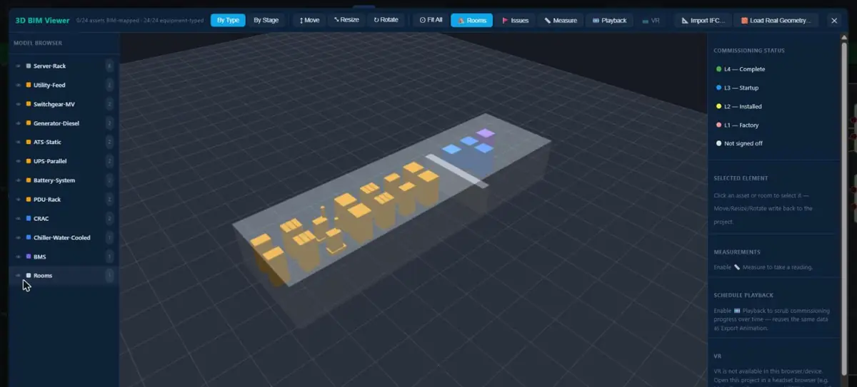 1234
1234- Model browser: equipment types, with the number of each
- Move, resize and rotate an element
- Playback: scrub commissioning progress over time
- Colour legend for stage L1 to L4
The 3D BIM Viewer (rail button) renders the project as a real Babylon.js scene. Each asset picks its own real-world model from the 3D Model dropdown in its side panel (the Resize 2D footprint to the model tick under it decides whether the pick also sets the asset's canvas size; untick it to keep the canvas as drawn) — every model in the library is offered to every asset, grouped into categories (e.g. "Distribution Boards", "Switchgear", "Placeholder / Testing"); models whose type suggests they fit the asset's own equipment type are simply listed first within their group and marked "(suggested)" — this is a sort hint only, never a restriction, since a suggestion based on equipment type can be wrong for a given real installation. Most models are hand-measured OBJ geometry; the library also accepts glTF/GLB models (a GLB entry loads asynchronously the first time it's picked, so its real geometry can take a moment to appear after a placeholder box, rather than blocking the rest of the scene).
Adding a new OBJ model — no code changes needed. Drop a new .obj file into the app's equipment-meshes/ folder and rebuild+redeploy — that's the entire workflow now. Every .obj file in that folder is picked up automatically at build time; a file with no hand-curated entry appears in the 3D Model dropdown under a new "Auto-detected" category with a generic name derived from its filename, and — since nothing has told the app which equipment type it represents — it is never auto-picked for any asset, only ever chosen explicitly from the dropdown. This is meant for quick visual checks of a new/candidate model; promoting one to a real curated entry (proper name, category, suggested equipment type, bay count) is still a manual step a developer does in code. The importer accepts both pre-triangulated and non-triangulated (quad/n-gon) OBJ exports, and auto-detects between the two source unit/axis conventions seen so far (CAD tools exporting in millimeters with Z as the up axis, and general-purpose modelers like Wings 3D exporting already in meters with Y as the up axis) from the file's own geometry — no per-file configuration is needed for either.
Generic data-centre models (13.8 kV down to 400 V). The library ships a ready set of generic equipment models, each pick-able for any asset: MV switchgear bay (13.8 kV class) and a compact ring-main unit, a neutral earthing resistor, cast-resin and oil-immersed 2500 kVA transformers, a 2 MVA diesel generator set (open skid and 40 ft container), an LV switchboard bay (400 V), a static transfer switch cabinet, a 1000 kVA UPS lineup with its battery cabinet, a floor PDU and a remote power panel. They sit under the categories Generic MV (13.8 kV), Generic Transformers, Generic Generators and Generic LV (400 V). They are original, simplified shapes drawn to realistic overall sizes taken from public manufacturer documents where available (the picker shows each model's size), and to a typical size for the equipment class where not; they are stand-ins for layout and visualisation, not a vendor's product and not for clearance or arc-flash studies. Switchgear bays are one bay each; set the bay count to tile them into a lineup. Every model is made of named parts, so once exported as OBJ it stays editable.
Position and rotation in the 3D view are edited two ways: dragging the move/rotate gizmo on the selected asset, or typing exact values into the numeric Pos X/Y/Z (meters) and Rot X/Y/Z (degrees) fields next to the gizmo controls — both stay in sync with each other. These 3D placement values are intentionally separate from the asset's 2D canvas position and size: correcting an asset's orientation or position in the 3D scene never moves, resizes, or otherwise changes its 2D canvas icon. A model's default orientation as authored is not auto-corrected — if a model sits rotated wrong when first placed, rotate it into place once via the gizmo or the numeric Rot fields; that correction is then remembered for that asset. If the project has any elevated platforms configured, moving a room or asset over one in 3D interacts with automatic platform elevation — see Elevated platforms below for exactly how a manually-set position and a platform's height combine.
Assigning a model to many assets at once. Select several assets (Shift+drag on empty canvas, or Ctrl/Cmd+click) and press Edit Properties… in the selection bar. The side panel changes only the fields you touch, for every selected asset in one undoable step: Equipment Type, 3D Model (with the choice to resize each 2D footprint to the model), Model Scale (%), the 2D footprint in metres and the section count — and, under their own headings, rated power, demand and scenario timings, target date, temporary / excluded-from-gates, boundary role and management impact, manufacturer and model number, and — when every selected asset follows the same engineering schema (all switchgear, all two-winding transformers, all generators …) — each nameplate value of that schema plus its source. Typed engineering values are merged into each asset's own: only the values you enter are written. A field shows the shared value, or mixed when the assets differ. Rooms in the selection are skipped, and the Narrow selection to type buttons keep only one equipment type — handy for giving every generator the same model. 3D models are not carried by BIM/IFC import or export, so this is where they are set in bulk.
Rooms are selectable and editable in 3D the same way: click a room's translucent volume (or pick it from the Rooms group at the bottom of the Model Browser) and the Move/Rotate gizmos and the numeric Pos/Rot fields act on the room. Clicking a piece of equipment that sits inside a room still selects the equipment, not the room around it. As with assets, a room's 3D placement is separate from its 2D canvas footprint; its wall height is still set on the 2D side panel.
Real IFC geometry replacing the placeholders. 🧱 Load Real Geometry… renders an .ifc file's actual 3D elements alongside the canvas-derived boxes. Once loaded, the 🫥 Hide Covered (N) toolbar toggle (on by default) hides the placeholder box/model of every asset whose BIM/IFC identifier matches an element in that file — an asset counts as matched when its IFC link GUID (from 📐 Import IFC…) or its BIM Mapping ID equals the element's IFC GlobalId. N tells you how many assets matched; 0 means the file's identifiers don't line up with any asset yet — link them first via Import IFC… or the BIM Mapping import. Unmatched assets, rooms and issue markers stay visible; toggling off or ✕ Clear Geometry brings the hidden placeholders back.
What the 3D view deliberately does not show. Connection lines between assets and package-manager blocks are not rendered in 3D — the 2D canvas is the place to read wiring and grouping; the 3D view is about the physical layout, its commissioning colours, and the schedule played back over it. (Earlier versions drew every connection as a 3D tube; that was removed for performance on large projects.)
Selecting equipment. Clicking any asset highlights it with a soft glow and shows its details in the right-hand panel. Assets of the same equipment type share their 3D geometry under the hood (which is what keeps large projects smooth); this is invisible in use — every asset still has its own colour, position, rotation and selection.
Elevated platforms. If the project has one or more elevated platforms configured (see Elevated Platforms above), any room or asset positioned within a platform's footprint on the 2D canvas automatically renders sitting on top of a visible deck at that platform's height, instead of on the ground. When a room or asset's canvas position falls inside more than one platform's footprint (overlapping footprints), it renders on whichever of those platforms is HIGHEST — never the first one found or an average of the two. There is no per-asset switch for any of this — it's based purely on where the room or asset sits on the canvas relative to each platform's footprint. This applies just as much to a room or asset you've manually repositioned in the 3D view (dragging its Move gizmo, or typing exact Pos X/Y/Z values — see above) as to one you've never touched in 3D: whichever platform's footprint contains its X/Z position — its 2D canvas position if you've never moved it in 3D, or its dragged/typed 3D X/Z if you have — that platform's height is always ADDED on top of whatever Y (height) you've set, never used to replace it. The numeric fields describe the asset the way a person on site would: Pos X/Z are the centre of its footprint (the point the Rotate handle turns it around — a corner would move every time the asset is rotated, so it is not used), and Pos Y is the height of its bottom above the ground, deck included — 0.00 means standing on the ground, 3.00 means standing on a 3 m platform, and typing 3.2 there lifts it 20 cm off that deck. The value shown is the value taken. Dragging an item in the 3D viewer no longer freezes it below a platform the way it once could — its height becomes an offset added on top of whichever platform applies to wherever you dropped it in X/Z. This is intentional and locked in: there is no toggle to keep a purely manual height while staying inside a platform's footprint — the only way to get full manual control over height is to place the room or asset's X/Z position outside every platform's footprint entirely.
VR walkthrough
The 🥽 VR toolbar button opens the same project as an immersive walkthrough in a VR headset — moving and teleporting, the live status badges, the hand-held menu with the Management pages and the selected asset's issues, checklists and documentation, the site board with its blockers and time scrub, the platform warp chain, and comments and status changes on issues from inside the headset. It has its own manual: VR Walkthrough Manual in the Help library (❓ Help → VR Walkthrough Manual), which also covers the desktop preview (🥽 Preview VR menu on desktop in the right-hand panel's VR section, or Ctrl+Alt+V) and troubleshooting.
Checklists
Checklists are separate from documentation: step-by-step Pass/Fail/N/A test scripts executed on site, with no required/optional distinction per item (unlike documentation). Every equipment type ships with a real starting template (never a blank list); the Checklist Manager lets you add, edit, or remove steps per equipment type and stage, and applies the change to every not-yet-locked asset of that type automatically. A stage can also hold "Section" rows — display-only headers with an optional caption, used purely to group and label the real Pass/Fail/N/A items underneath; they carry no result and are excluded from every completion count. A line item can also be set to "Text" instead of the default Pass/Fail/N/A — a free-text line for a question that needs a typed answer rather than a result (e.g. "Describe cable condition"); it reuses the same notes field as its answer, has no Pass/Fail/N/A buttons at all, and counts as resolved once that answer is non-empty. Leaving the Type column blank or unrecognized always falls back to a normal Pass/Fail/N/A item.
Calculation column holding faultLevel, voltageDrop, loading, generatorStepLoad or upsAutonomy). On the asset's checklist the step shows ▶ Run calculation: Dirac calculates from the project's engineering data, writes the working into the step's notes and sets Pass or Fail from the result (logged in the audit trail; tap another result to overrule it). If data is missing, or there is no rating to compare with, the notes say so and the result is left as it was. Everywhere else (mobile, VR, reports) it is an ordinary Pass/Fail step.Additional checklists
Beyond the one equipment-type-driven checklist per stage, any asset can carry any number of extra, asset-specific checklists ("scripts") — added, filled Pass/Fail/N/A, and completed independently from the same Checklist screen. Every additional checklist must be completed, alongside the main checklist, before the sign-off gate treats that asset+stage's checklists as done. "Sync to equipment type" propagates one additional checklist to every other asset of the same equipment type as its own separate checklist entry (matched by a stable id on re-sync) — it is never folded or merged into the shared main template or into another additional checklist. This is available on mobile as well as desktop (see "Mobile" below): desktop is where checklists — main and additional — are authored, mobile is where field users fill them in.
Separately, an additional checklist can be explicitly assigned to a chosen set of other assets via its 🔗 Assign to assets button, shown next to its name alongside a 🔗-count badge once linked. Unlike the one-shot "Sync to equipment type" above, this creates a persisted, ongoing group: adding or deleting an item on that checklist reflects automatically to every asset in the group, regardless of which member's copy you edit — while each asset keeps its own independent Pass/Fail/N/A results, notes, and completed state. A checklist never explicitly assigned this way is completely unaffected; removing one asset from the group just shrinks it, and it dissolves once fewer than two assets remain linked.
Room checklists
A Room is the lightweight canvas construct used for civil/electrical work that doesn't fit the 4-stage Asset commissioning model — an earthing grid, a manhole's electrical/mechanical work, or similar site-scoped work with no equipment type of its own. A room can optionally carry its own checklist (its properties panel's "Room Checklist" section) — pick a name and which commissioning stage it applies at, and it's automatically shared with every asset currently positioned above that room on the canvas, using the exact same fully-shared-checklist mechanism as "Additional checklists" above. Moving an asset onto or off the room's footprint updates that sharing automatically the next time the room's panel is opened.
Sign-off
Signing off a stage requires, in order: every required documentation item and checklist step complete, no open critical issues against the asset, and a sign-off password/certificate plus confirmation that the signing user actually belongs to the party group being signed off as. A stage requiring more than one party (joint sign-off) is only fully closed once every required party has signed.
Where a project genuinely needs to proceed despite an outstanding item, an authorized user can force a sign-off — doing so raises a real issue against the asset documenting exactly what was outstanding, rather than silently bypassing the record.
Tagging checklist — one sign-off for a group of assets
Some customers ask for fewer taggable assets: not fewer assets, but less paperwork — several assets share their checklists and are signed off together. Every asset still exists and is tracked on its own; only the sign-off act is shared. To set this up, open a fully-shared (🔗🔗) checklist at the stage in question and press 🏷 Make tagging (admin only). That checklist now carries the stage sign-off for every asset under it: their own Sign Off buttons for that stage disappear and are replaced by a link to the checklist, and the checklist's tab shows a 🏷 mark.
On the tagging checklist you will see a sign-off panel listing every member asset and one Sign Off … as <party> button per required party. Think of the tagging checklist as the final confirmation before the sign-off act: it must be completed itself, and then every member asset is put through exactly the same checks as an individual sign-off — its previous stage signed, no open critical issue, its upstream feeds commissioned on the final stage, and every checklist (its own, every shared one) and every required document at that stage complete. A hard blocker on any one asset blocks the whole group, and the message names the asset. Incomplete checklists or documents behave as they do for one asset: the sign-off becomes a forced one with a reason — and here that raises one project-level issue, tagged with every asset in the group and listing each asset's gaps, rather than one issue per asset. That raised issue is what excuses the missing item. The same password re-authentication and certificate check apply. Once signed, each asset carries its own ordinary sign-off record marked "via tagging checklist", so gates, the schedule, handover, reports and VR read it exactly as any other sign-off.
Rules: one tagging checklist per stage, and an asset can belong to only one tagging checklist per stage — the app refuses a second and names the conflict. A room's own checklist can't be tagging (its members change automatically as assets move). Undo is done from the checklist, for every asset signed through it together; an asset that was signed individually before the checklist became tagging keeps its own record and its own Undo. Group sign-off is desktop-only; the mobile field interface shows the note. An asset with no tagging checklist at a stage signs off exactly as before — nothing changes for it.
Sections — seeing the group as one thing
A tagging checklist is also a section. Every asset in it keeps its own requirements, its own sign-off and its own stage colour (an asset at L2 is still yellow); the section adds one thing on top, its own state, shown on the canvas as a dashed ring with a small badge in a colour that is not one of the stage colours, so the two never get confused. The badge counts up while the section is gathering (for example 2/4: two of four assets have the previous stage signed), reads ready once every asset can be tagged, tagged once the tagging checklist is completed and the assets await sign-off, and signed when every asset has the stage signed. Hover an asset to see the section's name and members. In the Tracker, an asset under a tagging checklist shows the same line with the planned date when a schedule exists.
When assets of one section are wired to each other (one feeds the next) the final-stage check no longer stalls the group on itself: the others in the section are counted as signed in the same act, while anything outside the section that is not yet commissioned still blocks, exactly as for a single asset. Nothing is stored for a section and a project with no tagging checklist has no sections: it looks and behaves as it always did.
Parties
The dedicated Parties screen (rail button) assigns a responsible party per stage per asset, project-wide. Massive Dynamic enforces genuine joint/multi-party sign-off — a stage configured to require two parties (e.g. CX and the Facility Owner) is not considered signed off until both have actually signed, not merely displayed as requiring both.
Issues
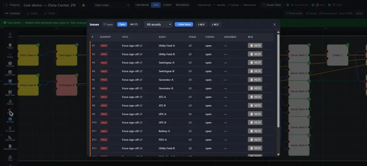 12345
12345- Asset filter, including project-level issues
- Raise a new issue
- Import or export BCF
- Severity: critical and high block sign-off of the asset
- One-click Non-Conformity Report
Project-level issues. An issue does not have to belong to one asset: in the Issues window's + New Issue form, choose Project — not one asset as the asset and the issue is raised against the project itself — a permit, site access, a missing drawing set, anything that is nobody's single piece of equipment. Optionally tag the assets it concerns (any number, or none). A project-level issue is listed, counted, filtered, reported and commented like any other and shows as Project in every list, with its tagged assets beside it; it appears on each tagged asset's own issue list (in the Tracker, on the phone and in the headset), but it never blocks an asset's sign-off gate, draws no 3D marker and appears on no badge — only an asset's own critical issue does that.
Importing issues from BCF / ACC. Issues that live in Autodesk Construction Cloud, Navisworks, Solibri, BIMcollab or any other tool that speaks the buildingSMART BCF format (BCF-XML 2.0, 2.1 and 3.0 are all read) can be brought in as a file: export the issues there as .bcf (or .bcfzip), open the Issues window here and click ⬇ BCF. The file is read in your browser and every topic is listed before anything is written: its title, its status there and the status it will get here (open / draft / in dispute → open, in review / in progress → in progress, answered / resolved → resolved, completed / closed → closed), and the asset it will be linked to. A viewpoint that selects an IFC element whose GlobalId matches one of your assets links to that asset outright; otherwise the link is found from the topic text — "Missing FAT : K30+S1 / SAS Panel" links to the asset named K30+S1; a green dot means the name was in the title, an amber half-dot means a looser match worth a glance, an empty circle means nothing was recognised and the issue becomes a project-level one. When a topic names several assets it becomes a project-level issue tagging all of them. Change any link in the dropdown before importing. ACC exports rarely carry IFC GUIDs, so for ACC the text is what matters.
What comes across: title, description (with a line naming the source, the original author, assignee, due date, status, stage, labels, links and documents there), status, priority as severity (medium when the export carries none), the creation date and author, the assignee's e-mail as free text, and the stage when the BCF stage names one of this project's stages ("L2", "IQ", or the full stage name). Snapshots become the issue's photos (downscaled to 1600 px, so a 400 MB export becomes tens of MB in storage); comments become the issue's Activity with their original date and author. Everything else the standard carries — labels, reference links, document references, related topics, BIM snippet, the IFC model files the topic was authored against, and each viewpoint's camera, component selection, clipping planes and lines — is kept on the issue exactly as it arrived, so exporting later (below) hands it back unchanged even though the app itself does not display cameras. Imported issues show an ACC (or BCF) chip in lists, and the issue form shows the origin line read-only.
Re-importing a newer export is safe. Each imported issue remembers its BCF topic GUID: importing the same ACC project again updates title, description, status and assignee on the issues it created earlier, adds only the comments and snapshots that are new, and keeps everything you added here (CAPA fields, NCR, photos, the asset link, a severity you raised). The preview marks those rows update instead of new. Untick Only topics that are still open to include completed ones; tick Only topics linked to an asset to skip the general ones. What is imported never blocks a gate any more than a hand-raised issue would: only an asset's own critical issue does.
Exporting issues to BCF. ⬆ BCF in the Issues window writes an archive that ACC, Navisworks, Solibri, BIMcollab and any other BCF reader can open. Choose the scope (all issues, open and in-progress only, or the list's current filter), the version (2.1 has the widest support and is the default; 3.0 on request) and whether photos go along. Each issue becomes a topic: title, priority from severity, status, the person it is assigned to, the stage as text, the description followed by one context line only this app knows (asset, stage, severity, status, party, CAPA fields, NCR), its comments from the Activity feed with their authors and dates, its photos as snapshots, and — when the linked asset has an IFC GlobalId — a viewpoint that selects that element, so the other tool jumps to the right equipment. Issues that came in from BCF keep their original topic GUID, status and priority words (as long as the meaning was not changed here), labels, links, documents, related topics and the viewpoints they arrived with, so sending the file back updates the same topics there instead of creating new ones. Two honest limits: the app never invents a camera — an issue raised here has none, and because BCF 3.0 requires a camera in every viewpoint, its IFC selection is only written in 2.1; and documents that live inside the other system (internal document references) are named but not carried.
Filtering by asset. Every issue list has an asset filter: the Issues window's dropdown (All assets · Project-level · one asset), the Management View's Critical Issues tab, and the headset's Management → Issues page. Filtering to one asset shows its own issues plus the project-level issues that tag it.
Issues (CAPA) are logged per asset via a full popup form — the same modal for creating a new issue and for opening/reviewing an existing one — covering title, severity, status, description, resolution notes, and the CAPA fieldset (root cause, corrective/preventive action, CAPA approver, CAPA status, effectiveness-check date). Open critical issues block that asset's sign-off. An issue can be assigned to a responsible party (group) AND/OR any number of individual project members at once. Individual assignees are picked via a searchable chip picker rather than a full member checklist — already-assigned people show as small removable chips (with their real party badge(s) so it's clear who's actually being notified), and clicking into the search box below the chips shows a short dropdown of unassigned project members straight away (up to 8), which typing an email then narrows further, so the picker stays compact even on a project with hundreds of members. Issue-assignment emails link back into the project.
Any already-raised issue can generate its own Non-Conformity Report (NCR) — a "📋 NCR" button next to the issue (in the per-asset issue list, or the project-wide Issues table) opens a formal in-app report scoped to that one issue: asset, stage, severity, assignment, timestamps, description, resolution, and the full CAPA record, with an "Export XLSX" option. The report never covers more than the single issue it was raised from.
Opening an existing issue (never a fresh unsaved "New Issue" draft) shows an Activity section below the CAPA fieldset — a single chronological feed for that one issue, mixing the system-logged events (created, edited, resolved) with a chat-style thread of comments, so everyone involved in resolving the issue can see the full history and discuss it in one place instead of hunting through email or a separate chat tool. Posting a comment optionally lets you Ping specific project members (the same searchable chip picker used for issue assignment, just scoped to "who should be notified" rather than "who's responsible") — anyone pinged is emailed with the issue and comment, since Massive Dynamic's in-app notification bell is local to one browser and can't reach a teammate on another device. Comments and pings are stored in the same durable audit log as every other tracked action, so they can never be edited or deleted once posted, matching the rest of the audit trail's 21 CFR 11 §11.10(e) immutability.
Mobile Field Interface
Massive Dynamic has a dedicated Mobile Field Interface (/mobile — phone browsers are auto-redirected there, with a "Desktop site" link as an escape hatch) for on-site technicians: browse projects and assets, fill checklists, raise issues with photos, and see sign-off/energization status. It reuses the exact same project data and the exact same pure sign-off/checklist/issue logic as the desktop canvas — a project opened on mobile is the same underlying record, not a separate mobile schema. The escape hatch works both ways: on a phone or tablet the desktop view shows a 📱 Mobile site button in the user bar at the bottom-right corner (next to Sign out) that takes you straight back to /mobile — so a technician who switched to the desktop canvas from their phone is never stuck there. Note that a stage is signed off on the desktop only: the phone completes checklists and raises issues, but sign-off needs the documentation review that happens in the office.
Offline-first
Every tap applies instantly and durably queues on-device; a debounced background sync replays queued changes against the current server copy once things go quiet (or immediately on leaving the project), so this device's offline edits and any concurrent desktop edits coexist instead of one overwriting the other.
4 stage statuses
Each stage tile shows Not started → In progress → Checklist complete → Signed off. "Checklist complete" is a mobile-specific status, sitting between the other two, since sign-off itself isn't an action a field user can take here.
Checklists, incl. additional
Fills the main checklist and every additional checklist for the asset+stage, Pass/Fail/N/A plus notes, with the same auto-raise-issue-on-Complete rule as desktop.
Raise Issue, with photos
Full issue-creation form, same core fields as desktop's issue popup, plus a mobile-only camera capture step (resized before upload) for attaching photo evidence.
Sign-off is view-only on mobile
Mobile deliberately has no interactive Sign Off button. The real sign-off gate requires a live password re-authentication plus a certificate lookup, either of which can hang or fail on a marginal field connection; rather than ship a control that intermittently fails on site, mobile shows sign-off status only (the stage tile badge, and a "Signed off by" banner) — actually signing off stays a desktop-only action until an offline-safe reauth design exists.
Deliberately desktop-only
Documentation Requirements, and every template/authoring screen (Requirements Manager, Checklist Manager, Parties assignment, Management View, Scheduler, Dirac, 3D Viewer, IFC import), are out of scope for the field interface by design — mobile is for browsing, filling checklists, raising issues, and viewing status; desktop remains where the project is set up and administered.
Reports
Two report types exist today: a BIM Status Report (equipment-by-equipment commissioning/energization status) and a Validation Document generator that produces a full L1-L4 (or DQ-PQ) qualification-style report per asset, including an AI-drafted summary paragraph. Both are generated on demand from the project's current state — there is no separate, persisted report archive.