Check the design where the drawing already is.
Fault level, voltage drop, loading, generator step and UPS autonomy, calculated from nameplate data on the assets, with every assumption printed next to the answer.
What do you want to do?
Jump straight to the answer
What the engineering layer is
Dirac has always known how your single line is connected. It can also work out what the connections mean electrically: how much current a transformer carries, what the fault level is at a board, whether a run drops too much voltage, whether a generator accepts the load behind it in one step, how long a UPS lasts. It does this from three kinds of data you keep on the drawing: nameplate data on assets, run data on connections, and the stated load (Load MW) on the assets that consume power.
The rule behind every answer: the numbers come from tested calculation code, never from the language model's memory of formulas. If a value is missing, Dirac does not guess it silently. It lists exactly which asset and which parameter is missing, calculates what it can, and says what it assumed. Electrical comes first; mechanical and pharma-process equipment follow once their parameter lists have been reviewed with a commissioning engineer.
Where things live
| You want to… | Go to |
|---|---|
| Enter or check an asset's nameplate | Asset panel → Engineering block (under Scenario timing). Also the Asset XLSX (Eng … columns), IFC import, or "set nameplate uk_pct of Transformer-A to 11.5". |
| Describe a cable, busduct or line | Click the connection on the canvas → Run row. Also the Connections XLSX (Eng … columns). |
| State the load | The asset's Load MW field (the same one the switching scenarios use). |
| Ask a question | Dirac chat — the phrases are listed under Commands. |
| Get a test calculator page for a transformer | Dirac: "short-circuit test for Transformer-A", "back-to-back test Transformer-A with Transformer-B", or "transformer calculator". |
| Put a calculation into a test script | Checklist Manager → the step's Calculation select, or the Calculation column in the template XLSX. |
Nameplate data on an asset
Open an asset whose equipment type has an engineering schema (transformers, switchgear and boards, generators, utility feeds, UPS). Under Engineering you see one field per parameter, with its unit and limits, plus Schema, Source and Verified by. Fields that a calculation needs and that are still empty are highlighted. The last line tells you what the data is good for: "Ready for: fault level, loading" or "Ready for 1 of 3 calculations (generator step load still needs …)".
An asset of a type with no schema shows a "choose a schema" picker, so a custom equipment type can still carry transformer or switchgear data. Changing the schema on an asset clears its values on purpose, because parameter names differ between schemas.
Schemas — transformers
Two-winding transformer (Transformer-Power, -Distribution, -Isolation): rated power S (VA), HV and LV rated voltage (V, at the nominal tap), short-circuit impedance uk_pct (%, 1–40), X/R, HV connection (YN / Y / D), LV connection (D / Y / YN), vector-group clock 0–11, rated currents, CT primaries on both sides, and optional tap anchors (HV voltage and impedance at the highest and lowest tap and the active tap) used to interpolate the impedance for a tap other than nominal.
Three-winding transformer (chosen explicitly, since the equipment library has no separate type): reference power, HV, LV1 and LV2 voltages, the three pairwise impedances HV–LV1, HV–LV2 and LV1–LV2 (%), X/R, connections and clocks of all windings, rated currents and CT primaries. IFC has no three-winding property set, so LV1/LV2 values stay typed.
Needed for: the short-circuit test and back-to-back test pages (voltages, impedances), fault level (S, voltages, uk), loading (S).
Schemas — boards, generators, utility, UPS
Switchgear / distribution board (switchgear MV/LV/HV-GIS, distribution boards HV/MV/LV, MCC panels, busbar, busway, floor and rack PDUs): rated voltage Un (V), rated current In (A), rated short-time withstand Ik (kA) and its duration (s). Loading uses √3·Un·In as the rating; fault level compares with Ik.
Generator set (diesel, gas, bi-gas): rated apparent power (VA), power factor (0.5–1), rated voltage, subtransient reactance x″d (%, 5–40), X/R (blank = 20), step-load acceptance (% of rated kW the set takes in one block, 10–100).
Utility feed: nominal voltage at the point of connection, short-circuit power S″k (MVA, from the utility), X/R (blank = 10), contracted current.
UPS: rated apparent power, output power factor, output voltage, installed battery energy (kWh), usable depth of discharge (blank = 80 %), inverter efficiency (blank = 94 %), required autonomy (min).
Source, verified by, and what overwrites what
Every asset's engineering block records where its values came from: nameplate (read off the plate on site), datasheet, ifc (read from a model file) or typed (entered without a document). Verified by carries a name and the date it was entered. These matter on a test record: a calculation made from values nobody verified is a design check, not an acceptance result.
Reading nameplate values from an IFC model
When you import IFC metadata and link an element to an asset, the importer reads the element's property sets once and, at confirmation, maps them against the linked asset's schema. The import table has a Nameplate column; hover shows the values and the property each came from. What is read: for transformers Pset_TransformerTypeCommon (PrimaryVoltage, SecondaryVoltage, PrimaryCurrent, SecondaryCurrent, MaximumApparentPower, ShortCircuitVoltage — a complex number in %, giving uk as its magnitude and X/R as imaginary over real —, TransformerVectorGroup with the neutral flags); for generators MaximumPowerOutput (active power, divided by the power factor to get VA) and Pset_ElectricalDeviceCommon PowerFactor and RatedVoltage; for switchgear RatedVoltage and RatedCurrent (the upper bound of the bounded value). A zig-zag or non-standard vector group is refused with a note and the connections stay as they were; a generator power without a power factor is reported and nothing is invented.
Nameplate data in the Asset XLSX
The asset sheet carries Eng Schema, Eng Source, Eng Verified By and one Eng <parameter> column per parameter name in any schema (for example Eng S_VA, Eng uk_pct, Eng Sk_MVA). Rules on import: a blank cell keeps the current value; - removes it; enum values are upper-cased and validated; numbers accept a decimal comma when there is no dot ("6,0" is 6) and read commas as thousands separators otherwise ("2,500,000"); an unknown parameter column is ignored; an asset whose type has no schema and no Eng Schema cell is left untouched.
What data is missing
Ask "what data is missing for Transformer-A" or "engineering data for Transformer-A". Dirac lists the values the asset carries and, for each calculation that applies to its schema, the parameters still empty. The same logic produces the "Ready for…" line in the panel, so the two always agree. In every calculation answer, anything absent appears under Not included (missing data) with the asset or connection name and the parameter to set, so the fix is always one step.
Runs — cables, busducts and lines
Click a connection on the canvas. The Run row holds: kind (cable, busduct, overhead line; pipe or duct on the mechanical layer), length in metres, R and X per km, rated current, and — for a run where you do not have the datasheet — size in mm², material (Cu or Al) and the number of parallel cables (×n). Only connections on the operational layer that actually carry power are used by the calculations; control and mechanical connections are ignored by the electrical ones.
The Connections XLSX has the same fields as Eng Kind, Eng Length (m), Eng R (ohm/km), Eng X (ohm/km), Eng Rated (A), Eng Size (mm2), Eng Material (cu, copper, al, aluminium, aluminum) and Eng Parallel. Blank keeps the value, - removes it.
The cable library — R and X from size and material
If a run has a length and explicit R and X per km, those are used as they are — the datasheet always wins. If R and X are blank but size and material are set, Dirac estimates them and prints Assumed in the answer. R is the conductor resistivity (copper 17.241, aluminium 28.264 Ω·mm²/km at 20 °C) raised to the 90 °C operating temperature of the conductor, times 1.05 for the stranded conductor's maximum resistance in IEC 60228 class 2, divided by the cross-section, with a small skin-effect factor on large sizes (+1 % from 120 mm², +3 % from 240 mm², +8 % from 630 mm²). X is a typical value by size: 0.09 Ω/km up to 25 mm², 0.082 up to 70, 0.079 up to 150, 0.075 above for low voltage; 0.11 Ω/km above 1 kV. With n cables in parallel, R and X are divided by n.
| Size | R Cu (Ω/km) | R Al (Ω/km) | X, LV (Ω/km) |
|---|---|---|---|
| 16 mm² | 1.443 | 2.378 | 0.090 |
| 35 mm² | 0.660 | 1.087 | 0.082 |
| 70 mm² | 0.330 | 0.544 | 0.082 |
| 95 mm² | 0.243 | 0.401 | 0.079 |
| 150 mm² | 0.155 | 0.256 | 0.079 |
| 240 mm² | 0.099 | 0.163 | 0.075 |
| 400 mm² | 0.059 | 0.098 | 0.075 |
Fault level at a bus
"fault level at Switchgear-A", "short-circuit current at LV-Board-1". Dirac walks from the bus back up the drawing to every source that can feed it (a utility feed or a generator set; live sources preferred, up to eight paths), turns each element on the way into a per-unit impedance on a 100 MVA base — utility from S″k and X/R, generator from x″d, transformer from uk and X/R (when X/R is not on the plate, a typical value that rises with rating), cable from its R and X — adds the series chain of each path, and combines the paths in parallel. The result: initial symmetrical short-circuit current I″k, short-circuit power S″k, the peak factor κ = 1.02 + 0.98·e−3R/X and peak current ip = κ·√2·I″k, and a comparison with the board's rated short-time withstand when one is entered. Check value: a 10 kV bus on a 250 MVA utility gives 15.88 kA (c = 1.1).
Needs: utility Un and S″k; generator S, Un and x″d; each transformer's S, voltages and uk; run R and X where there are cables. Anything missing is listed and left out of the sum — which makes the answer optimistic, so the answer says so.
Voltage drop to an asset
"voltage drop at PDU-1" (add "pf 0.85" for another power factor; the default is 0.9). Dirac starts at the LV terminals of the nearest transformer upstream (or at the source, when there is no transformer on the way) and follows each run to the asset. For each run ΔU = √3 · I · (R cos φ + X sin φ), where I is the current of all the load beyond that run (from the stated Load MW and the power factor). The drops are added and compared with a 5 % limit (the usual total for a consumer installation, IEC 60364-5-52 Annex G). Worked example: 200 A at 400 V, power factor 0.9, one 95 mm² copper cable of 80 m: R = 0.0194 Ω, X = 0.0063 Ω, ΔU = 7.0 V = 1.75 %.
Assumptions printed with the answer: balanced three-phase, load lumped at the end of each run, nominal voltage at the start. Needs a length and either R/X or size and material on every run in the path, and Load MW on what the run feeds.
Loading of a transformer, board, generator or UPS
"loading of Transformer-A", "how loaded is Switchgear-A". Demand is the sum of the stated Load MW of the asset and everything fed through it, converted to VA with the power factor, against the rating: S for a transformer, generator or UPS; √3·Un·In for a board; the Generator Power Rating (divided by 0.8) as a fallback. The answer gives percent, MVA, current and headroom, and warns above 80 % (little headroom) and over 100 % (overloaded). If no Load MW is stated anywhere downstream, the answer says the demand is zero because nothing is stated, not because nothing is connected.
Loading after losing a source
"loading of Transformer-A if Transformer-B is lost". This does not assume that everything behind B lands on A. It runs the scenario engine — the same engine used for the switching scenarios — with B lost, and counts what really moves: automatic transfers that close, standby feeds on separate input ports that pick up their loads, generators that start. Loads that only a manual tie could pick up are listed as held (not counted), and loads that end up dark are named. The answer is the steady-state result of the transfer, not its timing; for timing, use the scenario simulator.
Generator step load
"step load check for Generator-1", "can Generator-1 take the load". Rated active power is S·cos φ. The one-step capacity is the generator's step-load percentage of that. The load it would pick up is the stated Load MW of the assets behind it. If the total fits in one step, the answer is "one step". Otherwise Dirac proposes a staging: blocks sorted largest first and grouped so that no group exceeds the one-step capacity. It warns when the total exceeds the set's rating (it cannot carry it in any number of steps) and when a single block is larger than one step (it needs a soft start, staged closing or a larger set). This is the ISO 8528-5 block rule; the frequency and voltage dip of the actual engine and governor is not modelled.
UPS autonomy
"autonomy of UPS-A", "how long will UPS-A run". Usable energy = installed battery energy × depth of discharge (default 80 %). Autonomy = usable energy ÷ (load ÷ inverter efficiency, default 94 %), in minutes, at the stated load and at full rated load, compared with the required minutes when entered. It warns when the load exceeds the UPS rating. It is an energy balance: no Peukert effect, no temperature or ageing derating, constant efficiency. Use the battery vendor's discharge table for the acceptance record.
Transformer test calculators
The library behind the standalone calculator pages: two-winding and three-winding short-circuit test (inject at reduced voltage on one winding with the others shorted: injected and winding currents, per-unit values, vector-group phasors, the 87T differential check with CT ratios), and the back-to-back test of two parallel transformers whose HV sides are paralleled on a remote bus through two lines (every loop node named, the open-winding induced voltage, the 87L line differential check per line). A three-winding transformer is combined as a star equivalent. Stated in the pages: impedances are combined as magnitudes (the convention of the original calculators; the parallel pages also show a complex loop impedance when X/R is entered), and a tap other than nominal takes its impedance by linear interpolation, on the tap's HV voltage, between the highest, nominal and lowest tap anchors.
The calculator as a page you can send
Ask Dirac for "short-circuit test for Transformer-A", "back-to-back test Transformer-A with Transformer-B" (Dirac finds the common bus on the operational layer and takes the two lines' R and X from the connections, or leaves the page's example values and tells you), or "transformer calculator" for a blank one. Add "for <name>" to prepare it for a recipient. The result is a single offline HTML file: all four calculators on one page, pre-filled from the nameplate data, with the working shown step by step. In the page you can switch kind, edit any value (the result recomputes), print or save as PDF, save the configuration as a JSON file and load it again.
A file prepared for a recipient carries a watermark ("Prepared for … · date · Confidential") and expires after 30 days by default; an expired file shows a message instead of opening. The values it was filled with, and any that were left at the page's example, are listed in Dirac's answer.
Calculation steps in a checklist
A checklist step can carry a calculation: faultLevel, voltageDrop, loading, generatorStepLoad or upsAutonomy. Set it in the Checklist Manager (the Calculation select next to the step) or in the template XLSX (Calculation column). On the asset's checklist the step shows ▶ Run calculation. Dirac calculates from the project's engineering data, writes the date, the working and the result into the step's notes, and sets Pass or Fail from the result — logged in the audit trail; tap another result to overrule. If data is missing, or there is no rating to compare with, the notes say so and the result is left as it was. On mobile, in VR and in reports it is an ordinary Pass/Fail step with notes. The record therefore carries the numbers it was based on.
How to read an answer
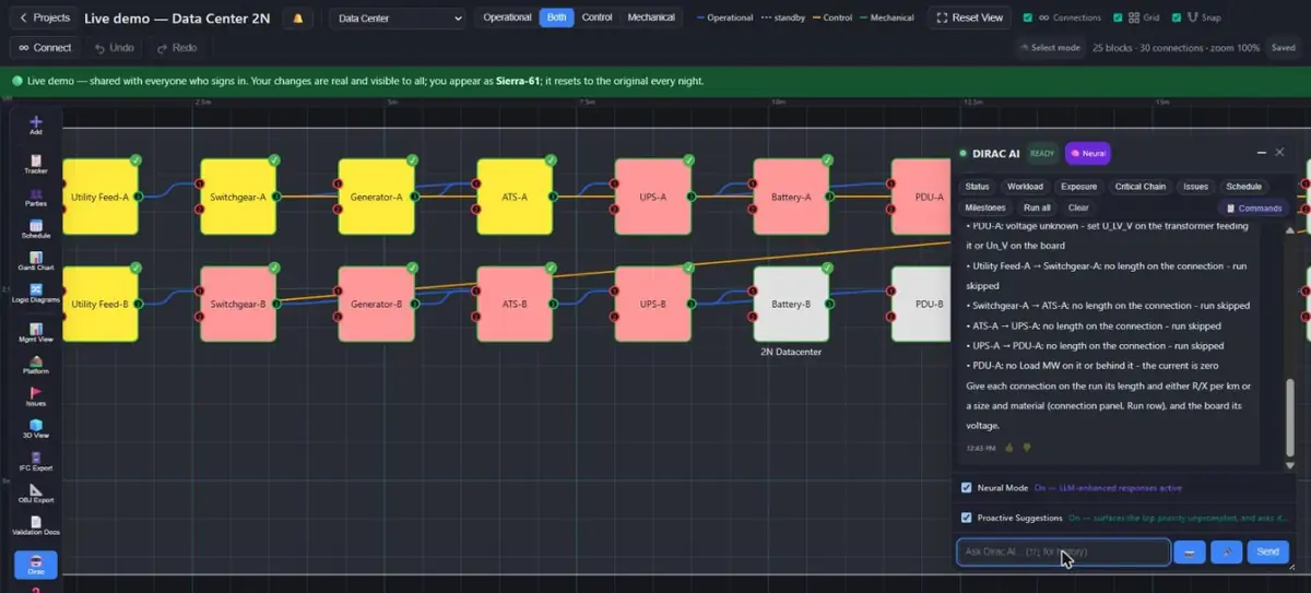 123
123- A missing voltage is named, with where to set it
- A run without a length is skipped, not assumed
- What to fill in to get a number
Every calculation answer has the same shape: a headline (the number and the verdict), the working line by line, warnings, Assumed (values taken from the cable library or a default such as X/R), Not included (missing data), and the basis (standard and simplifications). Behind the text Dirac also holds the same result as structured facts — the number, the verdict, the missing items — which is what lets it answer a follow-up such as "which of those are missing?" without recalculating by guesswork. A number in a checklist step, in the chat and in a calculator page come from the same function and are therefore equal.
Commands
| Say | Effect |
|---|---|
| what data is missing for Transformer-A | Read: the nameplate carried and what each calculation still needs |
| set nameplate uk_pct of Transformer-A to 11.5 | Changes the document (asks to confirm); enum and range checked; add "schema transformer-3w" to choose a schema |
| fault level at Switchgear-A | Read: I″k, S″k, κ, ip, rating check |
| voltage drop at PDU-1 [pf 0.85] | Read: drop per run and total against 5 % |
| loading of Transformer-A [if Transformer-B is lost] | Read: percent, MVA, A, headroom; with a loss, uses the scenario engine |
| step load check for Generator-1 | Read: one step or a staging |
| autonomy of UPS-A | Read: minutes at load and at full load |
| short-circuit test for Transformer-A · back-to-back test A with B · transformer calculator | Downloads the calculator page |
What these calculations do not do
| Calculation | Simplification, stated in every answer |
|---|---|
| Fault level | Three-phase, far from generator, c = 1.1, no motor contribution, no transformer correction factor, taps at nominal. Not a replacement for a short-circuit study on a protection-setting job. |
| Voltage drop | Balanced three-phase, load lumped at the end of each run, no motor starting, no tap-changer action. |
| Loading | Stated Load MW and one power factor; no diversity, no harmonics, no thermal ageing; after a transfer: steady state only. |
| Step load | Block-size rule; no frequency or voltage transient. |
| UPS autonomy | Energy balance; no Peukert, temperature or ageing. |
| Cable library | Typical values; reactance ±15 % with laying. |
A result that would decide an acceptance or a protection setting should be backed by the datasheet values and a study by a qualified engineer. Dirac's role is to make the first pass fast, to show every step, and to name every gap.
Standards referred to
IEC 60909-0 (short-circuit currents in three-phase a.c. systems); IEC 60364-5-52 Annex G (voltage drop); IEC 60228 (conductor classes and sizes); IEC 60287 (cable current rating and resistance); IEC 60076 (power transformers, typical X/R); ISO 8528-5 (generating sets, load acceptance); IEC 62040-3 (UPS performance); IFC4.3 property sets Pset_TransformerTypeCommon, Pset_ElectricGeneratorTypeCommon, Pset_ElectricalDeviceCommon (names as in the buildingSMART documentation).
Troubleshooting
"Ready for 0 of 2 calculations"
Open the asset and fill the highlighted fields. Typical gap: voltages and rated power on a transformer. IFC import or the Asset XLSX can fill them in bulk.
The fault level is lower than I expect
Look under Not included (missing data): a source with no S″k or x″d is left out of the parallel sum, so the answer is optimistic. Fix the missing values and ask again.
Voltage drop says "no run data"
The connection needs a length and either R/X per km or size and material. Click the connection and use the Run row, or fill the Connections XLSX columns.
"Loading … if X is lost" shows load as held
That load can only be picked up by a manual tie or has no standby. If the real scheme closes it automatically, check the standby tick, the separate input ports and that the assets are marked Available.
A checklist calculation step did nothing
The notes say why: usually missing data on the asset, or no rating to compare with. Fill the data and press Run calculation again.
Do the numbers match my own tools?
They should, within the stated simplifications. The library reproduces the example numbers of the four transformer calculators exactly and is tested against hand-worked values; if yours differ, compare the working lines, which show every intermediate value.