Switch it off. See what the plant really does.
Remove a source, trip a breaker, fail a breaker to open, and watch transfers, generators and held loads respond, from the same engine that checks the design.
What do you want to do?
Jump straight to the answer
What scenario testing is
Your canvas is already a single-line diagram: assets joined by operational connections, each connection carrying power from its from end to its to end. Scenario testing uses that drawing as a switching model. You tell Dirac that a source is lost, a breaker trips or an operator switches, and the engine works out — from the connections alone — what goes dark, what the automatic scheme would close to bring it back, in what order and after how long, whether generators have to start and how many, and whether two sources ever end up on one bus.
It answers the questions a sequence of operation (SOO) is written to answer: what happens when this incomer is lost? which breaker closes? how long is the outage? does the ring recover from the far end? do the generators start, and how many? how do we get back to normal? Because the answer is computed from your drawing, it is only as good as the drawing — this manual therefore starts with what the project needs before the first scenario.
The vocabulary
| Term | Meaning in the model |
|---|---|
| Feed | A connection seen from the asset it energises. An asset with two incoming connections has two feeds. A bidirectional link is a feed of both its ends. |
| Primary (closed) | The default state of every connection: the breaker is closed under normal conditions and the feed carries power when its source is live. |
| Standby (open) | A connection ticked Standby: normally open. It carries nothing until a transfer closes it. A ring's preferred open point is simply the one link in the ring marked standby. |
| Both ways | A connection ticked Carries power both ways (ring link, bus tie): the drawn direction is the normal-state flow, but power may run the other way after a transfer. Only the scenario engine reads this; ports, scheduling and exports keep the drawn direction. |
| Manual transfer | A standby feed whose relay is in Manual: a scenario never closes it on its own — it lists it as available for the operator. |
| Transfer delay | Seconds from the confirmed loss to this standby breaker closing (the relay's transfer timer). Blank = instantaneous. |
| Loss confirmed after | On a source: seconds the loss must persist before any transfer starts (the undervoltage pickup). Blank = instantaneous. |
| Start → ready | On a generator: seconds from the start command to the set being able to take load. |
| Generator Power Rating / Load (MW) | Capacity of a power source; demand of a load. The generator start is sized from these. |
| Memory | What an automatic transfer did: a standby feed it closed shows closed by a transfer — preferred open point; an incomer it opened shows opened by a transfer — normally closed. "return to normal" undoes exactly these. |
| Open transition | Break before make: the feed in service opens, then the other closes — a switching-instant outage. Every loss is handled this way; it is also the default for every other transfer. |
| Closed transition | Make before break: the other feed closes onto the live bus, both sources are paralleled for the parallel window, then the feed in service opens — no outage. Only for transfers made while both sources are live (a retransfer, an operator transfer), never for a loss, and only where the feed's transfer scheme says so. |
| Transfer scheme | The relay's programme as data on a standby feed, or the project default: transition (open / closed), parallel window, automatic retransfer delay, priority. See Transfer schemes. |
| Paralleling | Two live sources on one bus. An operator cannot create it by accident — a close onto a live bus is interlocked unless the feed's scheme is closed transition — and the model never creates it outside a closed-transition scheme; where it exists in the drawing (two NC incomers) or a timing race produces it, it is reported as a fault; a closed transition in progress is reported as information, with its window. The same source reaching a bus twice (a ring with no open point) is a loop. Several generator sets on a generator bus are generator paralleling — information, not a fault. |
Scenario mode — test without signing anything off
Switching tests used to need the plant marked Available and signed off to its final stage, because the model only treats an asset as present once it is. That made a test on a plant that is still being designed or built impossible without first pretending it was commissioned, and the test then changed the project. Scenario mode removes both problems: it runs every command in this manual on a private copy of the project held in memory.
simulate loss of Utility-A, fail to open feed from A to B, return to normal. The canvas shows what is energised and what is dark.enter scenario mode (as designed), start scenario as built, switch scenario to as designed and exit scenario mode do the same thing from the Dirac panel. Entering is not staged for confirmation, because nothing is written; it only opens the private copy. While you are in a scenario, what is going on says so in its first lines, together with the basis, so a result is never mistaken for the real project.simulate loss of Utility-A where the feed supplies another project) uses the same basis for every project in the group, not just the open one: As designed treats the other projects' assets as installed and commissioned too, and As built reads their saved state. Other projects are only read, never changed.Preparing a project
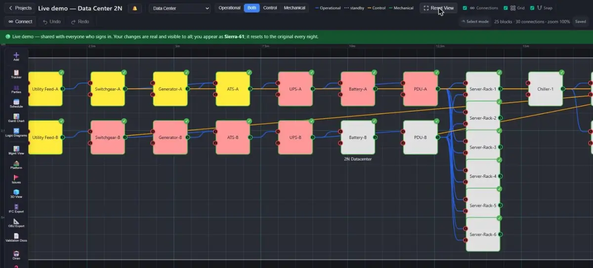 1234
1234- Layer switch: operational, control, or both
- Operational wire (blue) carries mains; control wire (orange) carries the signal
- An asset: its colour is its commissioning stage
- Tool rail: Dirac, Schedule, Management View, Issues, 3D
set default transition to closed with 2 s window, set default retransfer to automatic after 30 s) or per feed in the standby connection's panel under Transfer scheme (also the Connections XLSX columns Transition / Parallel Window (s) / Auto Retransfer (s) / Priority). Nothing set = open transition, manual retransfer. See Transfer schemes.Setting the normal state
Every script starts from the normal state and every group of tests ends in it. The normal state is: every normally closed breaker closed, every preferred open point open, all utility-fed assets on mains, generators off. Five commands put a copy there whatever the previous test left behind:
| Command | What it does |
|---|---|
force turn off mains on all assets | Clears every mains tick, generators included. A reset; no validation, no issues raised. |
switch Switchgear-A to Utility-A | Makes the named feed the asset's primary and opens its other feeds — the preference for each dual-fed board. Say it for each board that has a preferred incomer. |
energize downstream from Utility-A and Utility-B | Validated bulk energisation from the named sources in as many passes as needed; generators stay off unless named. Reports what it held back and why. |
return to normal | Undoes whatever automatic transfer the previous test left in effect (see Return to normal), or says "Nothing to do". |
open points | The switching picture: every open point, every memory line, every manual flag. Compare the count with your single line; there must be no warning lines in the normal state. |
parallel feeds | Every bus with two live sources. In the normal state only the boards your design feeds from two sources on purpose may appear. |
export connections to xlsx) and keep the file. It is the hard reset: importing it puts every flag back whatever happened, and clears every memory. You will rarely need it; "return to normal" and the five commands above are the everyday way back.Running a loss
simulate loss of Utility-A (also turn off mains in Utility-A; several sources: simulate loss of Utility-A and Utility-B; with a stated load: … with 20 MW load). The source disappears with the automatic scheme armed. The answer has a fixed shape:
- Forced off / Affected — the lost source and everything that went dark with it.
- Opened by the transfer — the incomers the scheme opened before closing anything (break before make): the dead incomer of each restored bus.
- Transfers — the standby feeds it closed to bring loads back.
- Backup generators started — which sets, and how the start was sized (see Generators).
- Auto-restored and Restoration paths — each load and the source it is now fed from.
- Available for MANUAL transfer — standby feeds in Manual whose source is live and whose load is still dark: the operator's decision.
- Still without mains — loads with no path at all.
- Paralleled or looped feeds — the check after restoration.
- Timeline and Outages — when timers or generators took part: one line per instant (lost, confirmed, opened, closed, generator started / ready, back, not restored), then how many assets were dark for how long and the longest outage.
- Model — the one-line pointer to the assumptions ("switching model" prints them).
Reading a timeline
Take a dual-fed board whose preferred incomer is lost, with a 0.5 s confirmation on the source and a 2 s transfer delay on the alternate, and a ring behind it whose open point has a 1 s delay:
t = 0 s: Utility-A lost — 93 asset(s) de-energisedt = 0.5 s: loss of voltage confirmed after 0.5 s — transfers initiatedt = 1.5 s: opened: Switchgear-A → RMU-1, … (the ring units' incomers on the dead side)t = 1.5 s: closed: RMU-2 ⇄ RMU-3, … (the ring open points)t = 1.5 s: 89 asset(s) back: …t = 2.5 s: opened: Utility-A → Switchgear-At = 2.5 s: closed: Utility-B → Switchgear-At = 2.5 s: 4 asset(s) back: Switchgear-A, …Outages: 89 × 1.5 s, 4 × 2.5 s; longest 2.5 s.Read it as the relays would act: each scheme runs on its own timer from the confirmed loss. Here the ring relays were faster than the board's transfer, so the ring units came back from the far side a second before the board itself — a coordination fact worth checking against the design: is that intended, or should the ring timer be longer than the main transfer? Because the incomers on the dead side were opened at 1.5 s, the board coming back on its alternate at 2.5 s does not parallel through the ring. The clock shows the delays you entered and nothing else — breaker operating times and protection timing are not in it.
loading of Transformer-A if Transformer-B is lost. Dirac runs this same engine with B lost and counts only the load that actually lands on A (automatic transfers, standby feeds on separate input ports, generators started); load that only a manual tie could take is listed as held. It needs ratings (S, or Un and In) on the assets and Load MW on what they feed - see the Engineering Calculations Manual in the application's help library.Manual mode and the operator
Tick manual transfer on a standby feed (asset panel → Feeds list, or the connection panel) to put its relay in Manual. A loss then leaves that bus dark and lists the feed under Available for MANUAL transfer; everything else the scheme can do, it still does. Generators are the last source: no set starts for a bus the operator could restore by closing such a manual feed from a live utility. And a generator is the only source the scheme can start — a utility feed that is off is lost until turn on mains in Utility-A. When it comes back it is live on every breaker that was never opened: the units that waited in the dark come back with it, through the closed links, without anyone closing anything.
The operator's commands are open feed from Utility-A to Switchgear-A, close feed from Utility-B to Switchgear-A and switch Switchgear-A to Utility-B. They are preferences: the model never remembers them and "return to normal" never undoes them. Opening a breaker by hand is a loss of voltage for everything behind it, and the relays downstream cannot tell an operator's open from a trip: with the relays in Automatic the scheme answers exactly as after a trip — the alternate closes after its delay, the answer carries the restoration and the timeline, the opened breaker stays open. So "open first, then close" by hand only works as a two-step sequence when the relay that would answer is in Manual; otherwise the scheme makes the close for you and your close reports "already closed". Put the relay in Manual first to switch by hand, exactly as on site. A feed opened by hand or by a trip is marked "opened by hand or trip" (its normal state is closed); a transfer that closes it again restores the normal state and remembers nothing. When your by-hand sequence ends with the drawing's own open point open, say so: mark feed from RMU-2 to RMU-3 as normally open — the design statement (the Standby tick as a command), which clears the marker so that the next transfer onto it is remembered and "return to normal" can undo it. A close onto a bus that is already live from another live source is interlocked: Dirac refuses it and names the feed to open first, as the programmed interlock in the switchgear would — unless the feed carries the closed-transition scheme, when the close is accepted as the first step of a closed transition and the answer names the feed to open within the window. switch does both in one step (the new feed primary, the others open) and says which it was: an open transition with the asset and its loads dark for the switching instant, or a closed transition with no outage.
To take the relay back to Automatic, untick manual transfer — the tick is shown on the feed whether it is open or closed, so this can be done before the retransfer.
Trips and lockouts
| Command | Meaning |
|---|---|
trip feed from Switchgear-A to RMU-1 | Protection opened the breaker. The loads behind it lose power and the automatic scheme answers on the clock as after a loss; the tripped feed itself is never re-closed by that run. Afterwards it stays open until closed by hand or by a later transfer. Not remembered as a transfer: "return to normal" leaves it to you. |
trip 86 on feed from Switchgear-A to RMU-1 (also lockout feed from …) | The lockout relay operated: the same, plus the relay in Manual. No automatic transfer re-closes it — a later loss elsewhere lists it as available for manual transfer and starts no generator for it. |
reset 86 on feed from Switchgear-A to RMU-1 | The lockout is reset: the relay is back in Automatic; the breaker stays as it is. Close it with close feed from … or let a transfer close it. If the scheme answered the trip by closing a standby (a ring link, say), return to normal after the reset re-opens that standby and re-closes this feed; while the 86 is still on, it is listed as left open (“locked out — reset 86 first”) and the standby stays closed. |
The difference between a trip and open feed: the trip is an event the scheme responds to; the open is an operator action that only cascades. The difference between a trip and simulate loss of X: the trip removes one feed, the loss removes a source with every feed it has.
Generators
Generators are the last source. They start only when a dead load has no utility path left — not even a manual one — and, with the playbook rule Cerberus on (the default), only when every board the generator bus serves is dark with no other way back (see The Switching Playbook). A set the operator holds with Hades (hold start of GEN-1) is never selected. When they do start, the set is sized in one of three ways, and the answer says which:
- Stated load —
… with 20 MW load: as many sets as cover the stated MW, plus one spare. - From the assets' ratings — the sum of Load (MW) over the de-energised assets, plus one spare.
- All sets — no load known at all: every available generator starts.
A dark generator bus with nothing behind it is not a reason to start sets — a lockout of one set's breaker on an idle generator bus starts nothing; the same lockout with a board on that bus starts the others for the board. The number running is always N+1. On the clock, the sets are started at the confirmed loss and are ready after their start → ready; the generator bus takes load only when the whole set is ready, and every further set that becomes ready parallels onto the running bus. A shortfall ("short by n MW") and a missing spare ("N+1 not met") are reported, never hidden. Several sets on one generator bus are shown as information, not as paralleling.
turn on mains in <utility>, or "return to normal") the load is put back on it at once - ties from the generator bus re-opened, utility incomers re-closed - and the running sets are stopped together, with their breakers re-opened, as soon as nothing that is a load would go dark without them. Switchgear, transformers, distribution boards, busbars and cables are distribution, not load: they never keep a set running. In the Manual scheme nothing of this happens by itself; the operator stops the sets. After a loss of all utilities, "return to normal" re-opens the ties from the generator bus once the utilities are back, re-closes the utility incomers, and then stops every running set together and re-opens their breakers — provided no asset that is on would lose its mains without them. It says "Generators stopped (n)". If something still depends on the sets (a utility is still dead, a tie could not be re-opened), the sets stay running and the answer names what would go dark; close the missing source and say it again. Sets are never stopped one by one, and an automatic retransfer (a feed with its own re-transfer time) never stops them. Several sets paralleled on their own bus are never a fault.The Switching Playbook
The scheme rules the engine applies are written down in one place: the Switching Playbook. Each rule has a name, is stored with the project, and can be switched off for a site whose scheme differs. They are ON by default, because the default is what the official sequences of operation of a 2N site require. show playbook lists them with their state; in the exported simulator they are the ticks in the header.
| Rule | When it is ON (default) | When it is OFF (the generic behaviour of earlier versions) |
|---|---|---|
| Cerberus the gatekeeper of the generators | Generators start only when every board the generator bus serves has lost its supply and none of them has another way back — a standby incomer, a tie, a breaker the operator could close. A one-board problem (one utility bus lost, a transfer that failed on one side) is left to the other board and to the ring self-healing, and starts nothing. Sets already running stay allowed. | Generators start whenever a dead load's best path runs through the generator bus. |
| Prometheus the bound breaker | A breaker locked out by an 86 is not something the operator could simply close — it needs the inspection and the reset first — so it is no alternative that keeps the generators off. | A Manual breaker counts as an alternative the operator could close, even after an 86. |
| Theseus the way around a stuck breaker | A stuck breaker (fail to open, both coils) blocks only the paths that run through its own device. The RMU rings still heal from their other side, on the ring's own timer counted from the loss. | A stuck breaker blocks every restoration path that starts at the same board. |
| Hades the operator's hold on a set | Not a toggle but a hold: hold start of GEN-1 (or hold start of all) keeps that set out of every automatic start until release start of GEN-1. A loss that needs the generators starts the other sets and names the held ones in the log; a hand start is refused while the hold is on. In the simulator the hold survives Reset all, like the timings. | |
Commands: turn cerberus off / turn cerberus on (the same for prometheus and theseus), set playbook to full (every rule on) / set playbook to generic (every rule off), show playbook. The older set official soo rules to legacy | official still works and means the generic / full preset. Only the rules that are OFF are stored, so a project with nothing stored runs the full playbook.
Rings
A ring is a chain of units between two boards with one link marked standby — the preferred open point. On loss of one board, the ring relays open the units' incomers on the dead side and close the open point, and power runs through the ring against the drawn direction to the units that lost their feed. When the lost board returns it meets open incomers, so nothing parallels; "return to normal" opens the ring point again and re-closes the incomers (the units are dark for the switching instant).
Moving the open point by hand, break before make: open feed from RMU-1 to RMU-2 (the unit beyond the new point is dark for a moment), then close feed from RMU-2 to RMU-3. "open points" then shows the new point and no memory, because an operator's open is a choice of the normal state. Closing the old point first would parallel the two boards through the ring — the interlock refuses it and tells you which link to open first.
Return to normal
return to normal undoes the automatic transfers in effect, feed by feed per its transfer scheme. Under an open transition (the default) it is two steps: step 1 re-opens every transfer feed whose loads will be live again once their incomers are back (generator-fed ties first; the running generator sets are then stopped together and their breakers re-opened once nothing depends on them — see Generators), step 2 re-closes every incomer a transfer had opened whose source is live and whose bus has no other live feed at that moment. Under a closed transition the order is reversed for that feed — the incomer re-closes onto the live bus first, the transfer feed opens after — and nothing goes dark. It reports both lists, how many assets were without power for the switching instant, that everything is back on afterwards, and whatever it had to leave alone:
- Left closed — a transfer feed whose load would stay dark (its incomer's source is still off): close the missing source first, then say it again.
- Left open — an incomer whose source is still off, or whose bus is still fed through a transfer feed that had to stay closed (closing would parallel the two).
It never touches what an operator did by hand, and it never closes two sources onto one bus outside a closed-transition scheme. With an automatic retransfer in the scheme you do not say it at all: when the source comes back (turn on mains in Utility-A), the feeds that carry the setting return to normal by themselves after their delay, and the answer reports "Automatic retransfer".
Returning only some assets to normal
A bare return to normal is project-wide, which is what you want while testing. To bring only some assets back and leave the rest of the setup as it is, use return selected to normal: on the canvas, Ctrl/Cmd+click the assets one by one — they need not be next to each other — or hold Shift and drag a box around them (a plain drag on empty canvas pans), then say it in Dirac. You can also name them: return Switchgear-A and Switchgear-B to normal or return to normal for Switchgear-A, Switchgear-B. Only the transfers that feed those assets are undone (and the incomers they had displaced are re-closed). Selecting a source such as a utility covers the boards it normally feeds. Generator sets are stopped only if they are in the selection too; otherwise they keep running and the answer says so. In the standalone simulator the named form works (return BUS to normal).
Transfer schemes
The relay's programme is data on the drawing, not an assumption of the model. One rule stands above every scheme: a loss of a source is always break before make. The loss may be a false signal — a VT fuse, a stuck contact — while the bus is in fact live, so the incomer that lost the voltage opens before the alternate closes, whatever the scheme says. The scheme governs the transfers made while both sources are live: the retransfer when the preferred source has returned, an operator's switch, a close feed onto a live bus.
| Setting | Where | What it does |
|---|---|---|
| Transition | Feed: connection panel → Transfer scheme → Transition; XLSX "Transition" = Closed / Open. Project: set default transition to closed [with 2 s window] / set default transition to open. | Open (default): break before make, a switching-instant outage, counted. Closed: make before break — the preferred feed closes onto the live bus, the two sources are paralleled, then the transfer feed opens; no outage. Presupposes the design verified synchronism (a 25 sync-check, or the same grid on both sides) — the model does not check it. |
| Parallel window (s) | Same places; XLSX "Parallel Window (s)". | The permitted parallel time of a closed transition. Informational: while both feeds are closed, parallel feeds reports ℹ️ closed transition in progress — open the other feed within N s and the Feeds list marks the feed; a parallel on a feed without the scheme, or on a bus whose two incomers are normally closed by design, is still a fault. |
| Auto retransfer (s) | Same places; XLSX "Auto Retransfer (s)" (Manual removes it). Project: set default retransfer to automatic after 30 s / set default retransfer to manual. | With a value, the transfer feed returns to normal by itself that many seconds after the preferred source has come back (turn on mains in … / simulate … on), in the order the transition says. Blank = manual: the operator says return to normal. |
| Priority | Feed only; XLSX "Priority". | Among several standby feeds into one bus, the lowest number closes first on a loss. Blank = the engine's order: fewest breakers, shortest delay, shortest path. |
A feed's own setting wins over the project default; nothing set anywhere means open transition and manual retransfer — how every project behaved before the scheme existed. switching model prints the scheme the project actually uses — the default and every feed with its own — ahead of the legend, so the legend never pretends a scheme the drawing does not carry; the Feeds list tags a feed's own scheme; open points states the default.
Testing a closed transition. With both sources live and the transfer in effect (after a loss and the source's return), return to normal on a closed-transition feed reports Closed transition — preferred incomer re-closed first, then re-opened within the window … no outage, and the count of assets without power is zero. To watch the window itself, do it by hand: close feed from Utility-A to Switchgear-A is accepted (ℹ️ closed transition in progress — open Utility-B → Switchgear-A within N s), parallel feeds shows the permitted parallel, open feed from Utility-B to Switchgear-A completes it. On a feed without the scheme the same close is refused — that is the interlock, and the test passes when it is.
Fail to open and fail to close (FTO / FTC)
A breaker that does not do what the relay told it to is a test input, set on the breaker and shown the next time the model operates it. It follows the sequences of operation of the project's three transfer schemes (RMU loop, generator/transformer pair, utility A / utility B pair). On a board with no tie breaker the two incomers are the pair: fail to open on the dead incomer, fail to close on the one that should close.
| Command | What it sets |
|---|---|
fail to open feed from A to B | Remote (default): the first attempt fails, the second (second trip coil, or the backup open path) works one retry delay later — default 1 s, the program transition time delay; set breaker retry delay to 2 s. A transfer on a loss slides by that delay and the timeline shows both attempts. |
fail to open feed from A to B in local | Local: one attempt only; the breaker stays closed and the failure does not clear. A transfer that needed it open is blocked (Transfer Control Lockout): the alternate never closes onto a bus still tied to the dead source and the load stays dark. An operator "open feed" or a trip leaves the feed in service, nothing lost. |
fail to open feed from A to B in remote, both coils | Both attempts fail: behaves as local, after the retry delay. On a ring the device is also isolated — its other breaker opens — and everything beyond it is restored from the other side. |
fail to close feed from A to B | The breaker stays open whenever it is closed; no retry. In an automatic transfer the close is not repeated without manual intervention and nothing is locked out (no Manual relay): the scheme goes on without that path, so on a board with a split utility bus a failed incomer close leaves the utility bus dead and the generator bus takes over (the tie opens, the generator feed closes); a ring node closes the breaker the scheme had just opened again. A "close feed" by hand fails the same way; a "switch" with the old source live puts the old incomer back (original condition). |
clear fail to open and fail to close on feed from A to B | Removes both (clear fto and ftc on feed from A to B is the short form). A failed close locks nothing out, so there is nothing to reset. |
Also settable per breaker in the connection panel (Fail to open / close (test)); the Feeds list and open points tag the breakers that carry one, and switching model lists them. A preferred-source change or switch while both sources are live makes one attempt with no backup path: a fail to open stops it and nothing moves.
Breaker failure is something else. In this manual "breaker failure" (BFP) means protection: a fault, the protection trips the breaker and the breaker does not open, so the whole bus behind it is cleared (every breaker that can feed it) and every return path is locked out. FTO / FTC are commands that do not work, set by the operator or the scheme. Breaker failure protection is not modelled in the app yet; the standalone simulator has it (breaker failure on feed from A to B).
The paralleling check
parallel feeds lists every bus with two or more live, carrying feeds and traces each to its root sources. Different roots → parallel, a fault. The same root arriving twice → loop (a ring closed with no open point, or two boards both on the same utility feeding one cubicle). All roots generators → generator paralleling, information. One of the feeds carrying the closed-transition scheme → closed transition in progress, information, with the window. Outside that scheme neither an operator command nor the model itself can create a parallel — the close is interlocked, a loss is break before make — so what the check finds is either in the drawing (two NC incomers by design) or the product of a timing race the scenario revealed. Every restoration, switch and trip ends with the same check.
Writing a test script
A good script is a spreadsheet, one command per row, run top to bottom, with the expected result written before the run and the actual result beside it:
open points and parallel feeds with the expected counts. Note the timers in force.; or then ("turn on mains in Utility-A; switch Switchgear-A to Utility-A; return to normal"); each is confirmed in turn. An "and" inside one command ("Utility-A and Utility-B") is never split.What the switching model assumes — and what it does not pretend to know
The same text is what switching model prints, and every switching answer ends with a one-line pointer to it.
- Loss of a source is ALWAYS break before make. A loss may be a false signal, so an automatic transfer OPENS the incomer that lost its source first, then CLOSES the alternate — whatever the transfer scheme says. The price is a switching-instant outage, reported as a count.
- The transfer scheme is data on the drawing, not an assumption. Each standby feed can carry a scheme (open or closed transition, parallel window, automatic retransfer delay, priority) or inherit the project default; the default of the default is OPEN transition. Open transition: "return to normal" and "switch" OPEN the transfer feed, then RE-CLOSE the preferred one (a momentary outage). Closed transition — allowed ONLY when BOTH sources are live (a retransfer or an operator transfer, never a loss) — closes the preferred feed onto the live bus first, then opens the transfer feed within the parallel window: no outage. "switching model" prints the scheme this project actually uses.
- Paralleling is interlocked, and otherwise a fault. "close feed" onto a bus that is already live from another live source is refused, as the programmed interlock would refuse it — unless the feed's scheme is closed transition, when the close is accepted as the first step of a closed transition and the other feed must be opened within the window (reported as ℹ️ closed transition in progress). Otherwise open the other feed first, or "switch". "parallel feeds" therefore reports what the drawing itself contains (two NC incomers in the design), a closed transition in progress, or what a timing race could produce; the one non-fault is several generator sets on a generator bus, shown as ℹ️ information.
- "simulate loss of X" = the source disappears with the automatic scheme armed. After the loss is confirmed (the source's "loss confirmed after"), each automatic standby feed on a restoration path closes after its transfer delay; Manual-mode feeds are listed for the operator and never closed. Generators are the last source: no set starts for a load that an operator could restore by a manual close from a live utility; otherwise the set is sized N+1 from the stated MW, from the de-energised assets' Load MW, or all sets when no load is known. A generator is the only source the scheme can start: a utility feed or tie-in that is off is lost until "turn on mains in X". A dark generator bus with nothing behind it is not a reason to start sets.
- "turn on mains in X" = the source returns: it is live on every breaker that was never opened, so everything reachable through closed feeds comes back (validated, L4 kept, no breaker closed — a transfer in effect stays in effect until "return to normal" or its automatic retransfer).
- "trip feed from A to B" = protection opened the breaker: it stays open until closed by hand or by an automatic transfer. "trip 86 on feed from A to B" = lockout: opened AND in Manual — no automatic transfer re-closes it until "reset 86 on feed from A to B" (or Manual unticked in the Feeds list).
- "open feed", "close feed", "switch X to Y" are operator actions: a change of preference, never remembered, never undone by "return to normal"; a close onto a live bus is interlocked (refused) unless the feed's scheme is closed transition. An operator's "open feed" is a loss of voltage for everything behind the breaker, and the relays downstream cannot tell it from a trip: the automatic scheme answers exactly as after a trip (Manual-mode feeds excepted) — put a relay in Manual first to switch by hand without the scheme reacting. A feed opened by hand or by a trip is normally closed: a transfer that re-closes it restores the normal state and remembers nothing. The drawing's normal state itself is set with the Standby tick or "mark feed from A to B as normally open / normally closed" (clears every memory and marker on that feed).
- "return to normal" undoes automatic transfers only, feed by feed per its scheme (open transition = momentary outage, closed transition = no outage), and never opens a breaker whose load would stay dark, closes one that would parallel two sources outside a closed-transition scheme, or opens the breaker of a running generator set (the generator controller stops the sets — "turn off mains in set" — not a retransfer; a stopped set's breaker is re-opened like any transfer feed) — those are listed with the reason. A feed with "automatic retransfer after N s" returns to normal by itself when its source comes back ("simulate … on"), after N s; other feeds wait for the operator.
- Timelines show the delays you entered (loss confirmation, transfer delay, generator start → ready, retransfer delay); breaker operating times, protection coordination (breaker-failure protection is a scenario you start, not a setting), sync-check, dead-bus logic beyond the interlock, and inrush are not modelled. Blank delays mean instantaneous.
- Only the operational (power) layer is simulated. Scenario results follow the operational connections and the mains state; the control layer — control power, controllers, interlocks wired through it — is assumed healthy and is not a condition of any result. The working assumption is that everything that controls the power path is functioning, so a loss, transfer or return-to-normal is judged on the power topology alone. A control-layer fault is not something this simulator can show.
- Every result is decision support from the data on the canvas, not a design study, a sequence of operation or a protection setting.
Sending the simulator to someone else
The same switching model can leave Massive Dynamic as one .html file that opens in any browser, with no server and no login. Two commands in Dirac (both are in the command list under Switching):
Simulator (export simulator). The same switching engine and the same screen as here: the whole single line on a map, click an asset or a line and use its buttons (every click is one command, printed in the log), the Scheme and Breaker failure settings, Return to normal, Run all commands and Download log. It contains the single-line diagram of this project and the switching settings only (names, positions, ports, ratings, delays, feed flags): no users, documents, schedule or stage sign-offs, and the page makes no network calls. Without a recipient it is a file for your own use: no watermark, no expiry.
To share it, say who it is for: export simulator for <recipient>. The file then carries four protections: the name in the header and repeated as a faint watermark across the page, a confidentiality line under the title, obfuscated code, and it stops opening after 30 days. Add expires in 14 days or never expires to change the expiry (it reads the recipient's own clock, so it is a deterrent, not a lock), anonymised to replace the asset names (UTILITY-1, GEN-2, SWGR-7 …) and the project name, and with manual to add this manual as a second tab.
Replay (export replay). The scenarios are run here and the results are recorded; the file only plays them back, step by step, on the diagram. There is no engine inside, so the recipient cannot type new commands and there is nothing in the file to copy but pictures and text. This is the safe version to send to anybody.
The file always reflects the project as it is when you export. After you change the drawing, the switching flags or the timers, export again.
Asking Dirac what is going on
Three read-only questions in the Dirac chat answer from the live project and the real engine rather than from fixed text. what is going on gives the picture: assets with and without mains, the utilities and generators, the transfers in effect, breaker failures, what return to normal would do right now (a dry run, nothing changes) and what is selected. why is Switchgear-A off lists that asset's feeds, which carry and which do not, and where the chain upstream ends; why are the generators still running gives the engine's reason for every feed it would hold back. why alone explains the last command Dirac ran: what it did, what it held back and why, and which assets ended up dark. These questions exist in Dirac inside Massive Dynamic only.
Run all commands. run all commands (or the Run all chip in the Dirac panel) runs every switching command the project supports through the real router on a throw-away copy, each from the project as it is now, and downloads one text log with, per step, how Dirac read the command, its answer and the state afterwards. Refusals are marked X and counted. Nothing in the live project changes. The exported simulator has the same thing as a button.
Command reference
| Command | Changes the project? | Use |
|---|---|---|
open points | no | Open points, memory lines, manual flags, multi-fed assets. |
parallel feeds | no | The paralleling check on the current state. |
switching model | no | The project's transfer scheme (default + feeds with their own), then the assumptions legend. |
set default transition to closed with 2 s window / set default transition to open | yes | Project default transition for both-sources-live transfers. |
set default retransfer to automatic after 30 s / set default retransfer to manual | yes | Project default retransfer. |
force turn off mains on all assets | yes | Reset to all dark (also … control …, … mains and control …). |
energize downstream from X [and Y] | yes | Validated bulk energisation from named sources; without names, from every utility feed and tie. |
switch X to Y / prefer Y on X | yes | Operator: Y becomes X's primary feed, the others open. |
open feed from A to B / close feed from A to B | yes | Operator: one breaker. An open is a loss of voltage downstream — the automatic scheme answers as after a trip. |
mark feed from A to B as normally open / … as normally closed | yes | The drawing's normal state of a feed (the Standby tick as a command); clears memory and markers. |
trip feed from A to B / trip 86 on feed from A to B / reset 86 on feed from A to B | yes | Protection trip, lockout, reset. |
fail to open feed from A to B [in local | in remote, both coils] / fail to close feed from A to B / clear fail to open and fail to close on feed from A to B / set breaker retry delay to N s | yes | Fail to open / fail to close test inputs (see Fail to open and fail to close). |
set scheme to manual / set scheme to automatic | yes | The scheme selector (the header switch in the simulator). Manual: a loss starts no generator set, closes no transfer feed, opens no dead incomer; nothing retransfers by itself. Automatic (default): the transfer schemes act. |
start GEN-1, GEN-2 / stop GEN-1 | yes | Start or stop generator sets by hand. A set that starts feeds only through closed breakers. A stop is refused, with the breakers to open first, if an asset would lose mains without the set. |
tick manual transfer on feed from A to B / untick manual transfer on feed from A to B | yes | The relay of one breaker in Manual: the scheme never closes or re-closes that feed by itself. The same as the Manual tick on the canvas. |
show playbook / turn cerberus off (prometheus, theseus; … on) / set playbook to full / set playbook to generic | yes | The Switching Playbook (also the ticks in the simulator header). Cerberus: generators start only when every board has lost its supply and none has another way back. Prometheus: an 86-locked breaker is not something the operator could simply close. Theseus: a stuck breaker blocks only the paths through its own device, so the RMU rings still heal (12 s). Every rule on by default; switch one off for a site whose scheme differs. set official soo rules to legacy | official still works as the generic / full preset. |
hold start of GEN-1 / hold start of all / release start of GEN-1 | yes | Hades: the set is left out of every automatic start until released; "start GEN-1" is refused meanwhile. Put the hold on before the loss — the scenario is computed in one go. Also the button in a set's click panel in the simulator. |
breaker failure on feed from A to B / reset all 86 / clear all breaker failures | yes | Protection with breaker failure: the fault is on the feed A → B, both ends trip, the breaker at A fails to trip, so every other breaker of bus A trips after the operating time (set breaker failure delay to 0.3 s); B's own breaker opens and B transfers like after any trip. Lockout is a site setting (set breaker failure lockout to upstream | all | none): by default the breakers that can bring power into bus A from outside get 86 and the feeders facing downstream trip only. Then reset the lockouts and clear the flag after the repair; "return to normal" closes what was tripped without lockout. |
simulate loss of X [and Y] [with N MW load] | yes | Loss with the automatic scheme armed, on the clock. |
turn on mains in X | yes | A source returns; feeds with an automatic retransfer in their scheme return to normal by themselves, the rest wait. |
return to normal | yes | Undo the automatic transfers, per each feed's transfer scheme. |
export connections to xlsx / import connections from xlsx | export no / import yes | Baseline and hard reset; bulk flags and timers. |
Every command that changes the project shows what it will do and waits for your confirmation first.
Operating by hand (scheme selector in Manual)
On site the transfer scheme can be switched off and the operator does everything. The scheme selector does that for the whole project: set scheme to manual. A loss of the utility then leaves the loads dark; no generator set starts, no standby feed closes, nothing retransfers, and an operator open feed is not answered by the scheme. Use set scheme to automatic to give the schemes back.
The by-hand sequence after a loss of the utility: start GEN-1, GEN-2; close feed from GEN-1 to GEN-BUS (and the other breakers out of the sets, then the tie onto the bus); the loads come back as each closed path reaches them. A close onto a live bus is still interlocked. The way back: turn on mains in UTILITY (the utility returns, the generators stay running); close feed / open feed to move the load back; stop GEN-1, GEN-2 once nothing depends on them (a stop that would drop a load is refused and lists the breakers to open first); or return to normal to do the whole way back in one go.
To make only some breakers manual and leave the scheme armed for the rest, use the Manual tick on those breakers (tick manual transfer on feed from A to B) instead of the selector. Ask what is going on at any point; it says when the selector is in Manual. Generator cool-down after a stop is not modelled: a stop is immediate.
Questions that come up
A loss did nothing — "No downstream loads were affected".
The lost asset feeds nothing that was on, or everything below it has a second primary feed (two closed incomers = already paralleled; check "parallel feeds"). Or the asset is not a source in your drawing: a source has no operational inputs.
Everything came back at t = 0.
No timers entered. The result is still right as a static answer; the ordering is the part that needs the design's values.
The ring did not recover from the far end.
The ring links are not ticked Carries power both ways, or the open point is not marked standby, or a unit's final stage is not signed off on the copy.
Generators started when I did not expect them.
Check whether the bus really had no utility path: a standby incomer marked Not Available, or a missing connection, leaves only the generator tie. If an alternate exists but is in Manual, no set starts — the bus waits for the operator. With Cerberus on they start only when every board is dark; show playbook tells you which rules are on.
How do I stop the generators from starting? I cannot type a command before the start delay runs out.
You cannot — the scenario is computed in one go, there is no moment in between. Decide before the loss: hold start of GEN-1 (or … of all) keeps the sets out of the automatic start; the log then says "held by the operator (Hades)" and names them. release start of GEN-1 lets them back in. The scheme selector in Manual holds everything, the sets included.
Only one board lost its supply and nothing started — is that right?
Yes, with Cerberus on: the other board is fine and the RMU rings heal from their other side (12 s), so the generators are not asked for. That is what the official sequences of operation of a 2N site say. If your site starts the sets for a one-board loss, turn cerberus off.
"return to normal" left something closed or open.
It says why: a source still off, or a bus still fed through a transfer feed. Turn the source on and say it again; it never guesses.
I opened a breaker by hand and the ring transferred by itself.
That is the relay doing its job: an open breaker is a loss of voltage downstream and the automatic scheme answers as after a trip. Put the relay that would answer in Manual first (Feeds list → manual transfer) to switch by hand in two steps; the answer to the open lists the transfers and the timeline either way.
"return to normal" left the generators running.
It stops them only when no asset that is on would lose its mains without them. The answer says which assets still depend on the sets — usually a utility that is still off or a tie that could not be re-opened. Fix that, then say "return to normal" again.
"close feed" was accepted onto a live bus — I expected the interlock.
That feed, or the project default, carries the closed-transition scheme: the close is the first step of a closed transition and the answer names the feed to open within the window. switching model shows where the scheme comes from; set default transition to open or the feed's panel removes it.
The transfer undid itself when the source came back.
An automatic retransfer is set — on the feed or as the project default. The answer to the turn-on says "Automatic retransfer … after N s". set default retransfer to manual or the feed's panel makes it wait for "return to normal".
"open points" shows a warning I did not cause.
A previous test's transfer is still in effect — the memory lines tell you which breakers. "return to normal" clears them; the normal-state commands clear everything else.